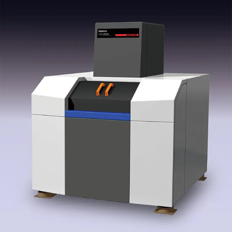
Features/Functions
Equipped with our own high resolution, multi-focus aperture tubes
- Multi-stage electromagnetic lenses and high-intensity filaments ensure ultra-sharp focus and high contrast. Guaranteed resolution of 0.4 µm (JIMA chart).
- The focus size can be selected from five levels: 0.4/0.6 µm for observing fibres, microcracks, etc., 1.0/2.0 µm for CT imaging and electronic semiconductor components, and 3.0 µm for assembled boards and BGAs.
Four functions in one unit with a wide range of measurement options.
- CT option (orthogonal/simple oblique CT) functionality can be added
- Heating system functionality (reflow simulation + real-time video storage) can be added.
※The CT and heating units can be switched by simply attaching and detaching the table. - Customised support is available for automated image processing and loader/unloader for transparent imaging.
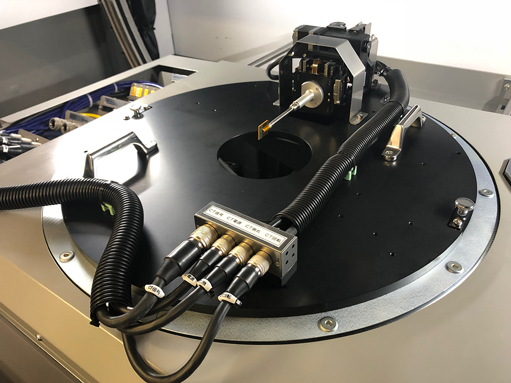
Orthogonal CT Units
High-resolution CT imaging is possible; cross-sectional data in three directions can be acquired in a single CT scan and any cross-section can be observed.
Mountable sample size
 :20mm×20mm 150g
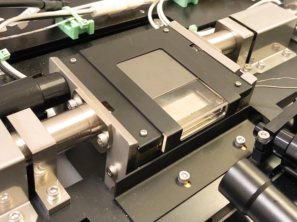
Heating unit
Real-time video monitoring of sample heating. Heating up to 400°C with halogen and hot air.
Temperature gradient settings from 0.1 to 5°C/sec.
Mountable sample size
:40mm×40mm 6mm thick.
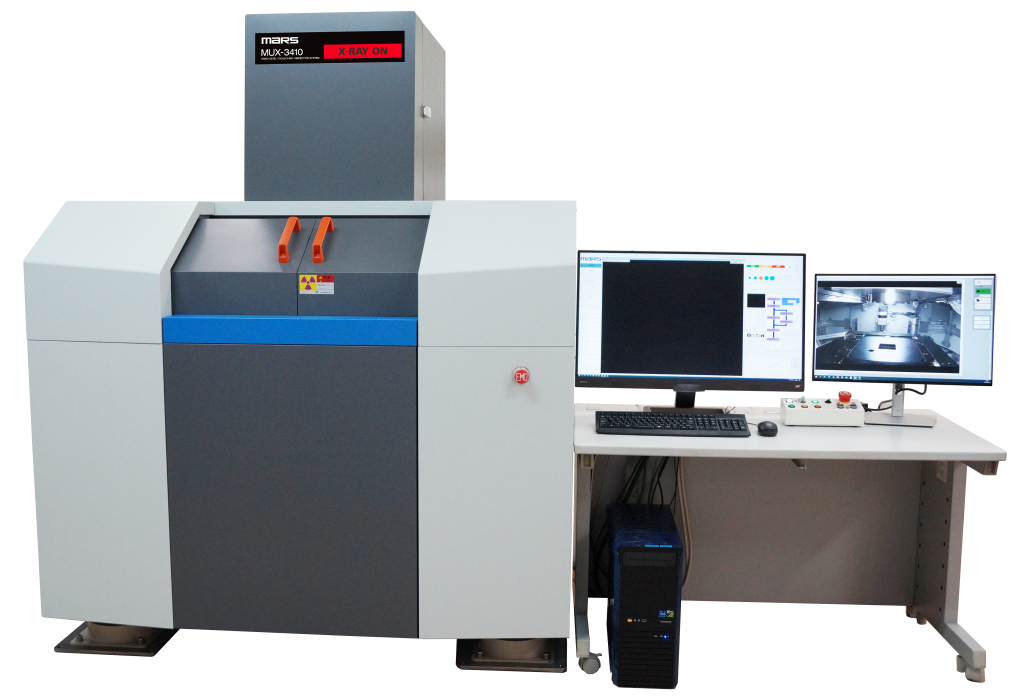
High-precision three-dimensional X-ray tilt CT imaging (MUX-3410).
- Complete with high precision stabilised orbit stage and control software.
- CT imaging at high magnification without destroying large specimens
Target area

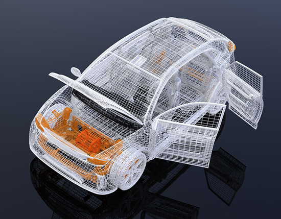
Target product
| Ceramic components | LED Components | Mounting (substrate) |
| Wafer | On-board sensors | Connector |
For enquiries about this product or to discuss its implementation, please click here.
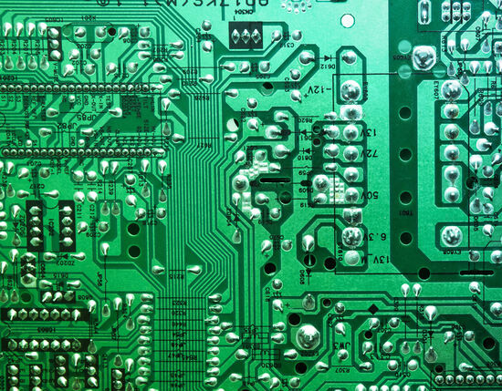
Imaging Sample
Multilayer IC Package
40 µm diameter Cu wire
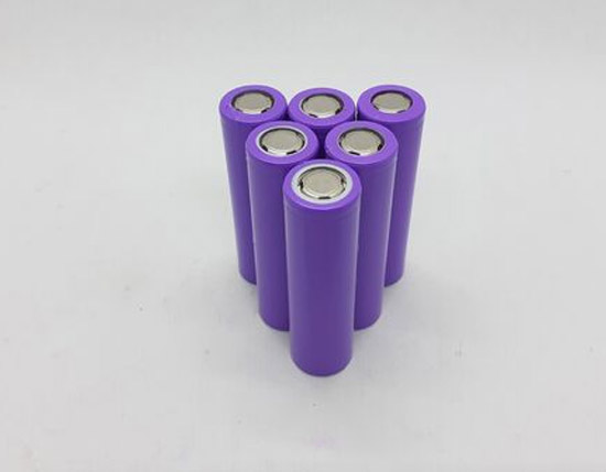
200 µm diameter BGA
Product Specifications
| X-ray source | Source type and X-ray power | Open tube type 20 to 130kV /10 to 200µA | |||||||
|---|---|---|---|---|---|---|---|---|---|
| Minimum resolution and focus switching | 0.4 µm (JIMA chart guaranteed) / 5 steps of 0.4-0.6-1.0-2.0-3.0 µm | ||||||||
| X-ray detector | 4-inch high-brightness image intensifier + 5-megapixel CMOS camera | ||||||||
| Detector tilt angle and position (FID variable) | T-axis -5° to 60° variable elevation 300 to 600 mm FID from the x-ray centre of gravity | ||||||||
| Geometric magnification (min-max) | 2.0x – 1200x (monitor magnification 7200x) * at minimum FID 300mm / maximum FID 600mm) | ||||||||
| Camera resolution (digital zoom not used) | 0.03 µm/pixel at 1200x geometric magnification (field of view size 0.06 mm x 0.05 mm) | ||||||||
| Sample stage | Sample table dimensions Load capacity | Diameter 400 mm (MUX-3410: 340×340 mm, viewing size 300 mm) 7 kg max. weight | |||||||
| Stage movement | X-axis ±150mm Y-axis ±200mm (MUX-3410: ±150mm) θ-axis ±360° (MUX-3410: -185° to 420°) | ||||||||
| Dimensions and weight | Main unit weight 1594 (W)x1787 (D)x1944 (H)mm Main unit weight 2200 kg (MUX-3410: 3000 kg) | ||||||||
| Utility | Power supply: AC200V ±10% 50A Class D Installation/air: 0.4-0.5 Mpa Φ6 mm pipe | ||||||||
Easy to use interface for beginners.

- The procedure navigation function allows even novices to easily perform transmission imaging and CT imaging.
- A full range of transmission imaging support functions, including an alignment function to simplify levelling of tilted specimens and two-point length measurement.
- The optical camera provides a full view of the inspection table and the table can be easily moved by clicking on the optical photo.
Displays the basic operation sequence.

A series of steps, from sample preparation to imaging to completion, are displayed in a flow.
Clicking along the steps makes it easy to perform the imaging.
Mouse-operated easy-operation
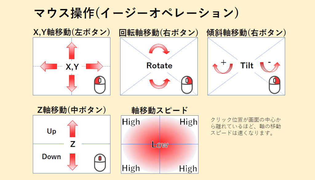
Focus size switching function

Click on the focus size on the control screen to change the focus size and take the picture.
Higher magnification and finer detail – small focus (0.4 or 0.6 µm)
Large area at low magnification – Large focus (2.0 or 3.0 µm)
Useful features
Sort function
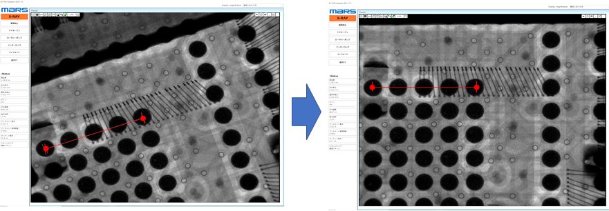
Calculates the angle of rotation between two points in the image and adjusts the image horizontally or vertically between these two points.
Optical mapping / X-ray mapping function
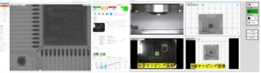
Optical mapping
The entire stage is captured by an optical map camera which detects the entire image of the sample on the stage. By clicking on the optical image, the viewpoint can be moved directly to the observed part of the sample.
X-ray mapping
This function automatically divides a large sample into several images and then combines these images into a single image (mapping image) from which an overall image is obtained.
The function creates a single image (mapping image) by stitching together each segmented image to create an overall image.
Two-point length measurement function
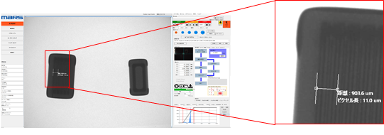
The distance between any two points on the screen can be measured.